Part One: Overview and Setup
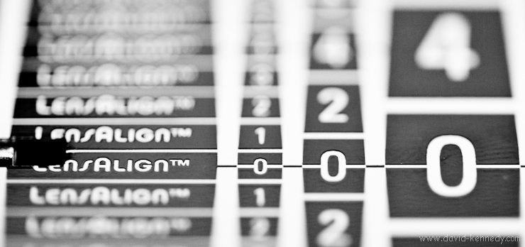
LensAlign Pro
Earlier this month, Michael Tapes, president of RawWorkflow, e-mailed me because he saw my mention of Datacolor’s product, aimed to complete with his LensAlign, the Spyder LensCal. He also referenced my account of working briefly with one of his company’s LensAlign Pro units this summer. Michael then offered to have a review copy of the LensAlign Pro sent to me for a closer look at this useful, if somewhat expensive, tool for properly calibrating the autofocus performance of a camera and lens.
While many manufacturers, including Canon, Nikon, Sony, and Olympus, now provide a means for end-users to calibrate the autofocus performance their prosumer and professional cameras via “autofocus microadjustment” (AFMA), none of them offered a tool for making these changes in a meaningful way.
LensAlign, then, is a platform for measuring the focus accuracy of a camera/lens combination. One takes this information and then, if necessary, change the AFMA to shift the depth-of-field (DOF) so that it straddles the “0” mark on the LensAlign ruler. I will explain the overall functionality (although I do not intend to re-create the wheel–the LensAlign manual is on the company’s resources page) and consider why one would purchase such a product.
Debunking the 1:2 Depth of Field Myth
One of my initial concerns about this process is that I’ve heard for years–from anecdotes in photography books to some of my professors in graduate school–that depth of field is split in a 1:2 ratio around the point of focus. That is, 1/3 of the DOF resides in front of where one focuses and the remaining 2/3’s lies behind it. But LensAlign is designed to make the DOF 1:1 in front and back of the focus mark, which seemed to go against the grain. Someone has to be wrong!
In researching this, I found a page of “Common photography myths,” and sure enough, number 14 was that DOF was 1/3 in front and 2/3 in back. Essentially, DOF is mostly 1:1 front to back. However, as magnification is decreased (distance from subject becomes greater, i.e. farther back in the frame), DOF slowly grows to become closer to the 1:2 ratio of lore. Then, as one focuses more towards infinity, the ratio becomes 1:∞, and hyperfocal distance is achieved.
The DOF ratio is not always 1:1, hence my saying “mostly.” For example, with wide-angle lenses, particularly at close distances, the split becomes 40% in front and 60% behind the focus mark. If you want to know more about how depth of field is calculated, you can find the formula here, and a list of known values for the circle of confusion of several camera models can be found here.
All this aside, I suppose if one desires a 1:2 ratio for depth of field, one can use LensAlign to shift it to one’s liking, but it is a choice to alter the way that things are designed to work for one’s creative needs, it is not “the way it should be.”
Inside the Box & Initial Setup
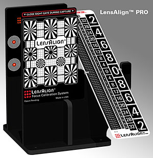
Upon opening up the white clam-shell box, one finds the main unit, and a postcard detailing how to set up the following components: its metal ruler, the “sight gate,” a magnetic on an adhesive strip for the “sight gate,” and four small, cylindrical magnets for use with the LensAlign’s “enumerator.”
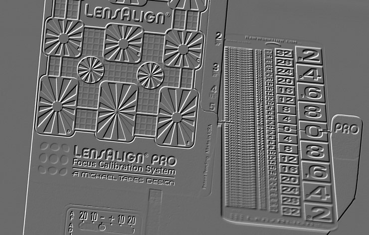
The body of the LensAlign Pro is made of four pieces of extruded sheets of PVC that have been cut with a router. Two vertical pieces are parallel to one another–the front containing a the focusing target that also holds the “0” mark of the LensAlign ruler. The rear vertical piece contains the bulls-eyes for making the unit square to the camera position. A third piece is perpendicular to the other two, and keeps them straight. All three are screwed into a square of PVC with a 1/4″ tripod thread in the center. To keep the two focusing pieces parallel to one another, and to prevent them from bending in transit, a length of poster tube is packed between them for shipment. Keep this piece in the event you ever want to travel with LensAlign Pro!
The ruler is a 9.5″ strip of metal, and it is how one gauges the focus calibration of their camera/lens. Every other part of LensAlign is designed to work to support this ruler. So, while in the initial setup the user concentrates on everything except the ruler, during the actual measurement stage, the ruler will be all that matters.
The sight gate is a plastic card that will slide up and down to open and close the bulls-eye’s in the front of the LensAlign. However, to make it slide, one has to adhere a magnetic strip on the back of it (it’s a little odd that the user has to do this, and I assume it has something to do with labor costs to produce LensAlign, but it is a trivial matter to do it one’s self).
Once set up, the main unit could be used on a tabletop, but a 1/4 inch thread allows it to be mounted onto a tripod. One could mount the unit onto a light stand, but for reasons explained later, it is better to have the unit on a tripod head that allows movements, such as a ball head.
The enumerator and the ruler
The ruler has various positions that it can be set to (and held in place by magnets). They range from virtually parallel to the imaging plane to almost perpendicular. However, the LensAlign documentation recommends beginning with the ruler at the third position, and my experience seems to confirm that this is usually a good starting point.
That said, I tend to use the “flatter” ruler positions, 4 and 5, just as frequently as I do position 3. The greater the distance between the camera and the LensAlign, the flatter the ruler should be, as it makes it easier to distinguish the boundaries of the DOF.
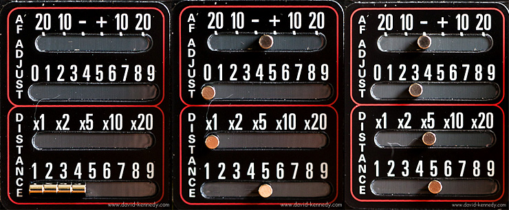
The enumerator is not essential for the operation of the LensAlign, but it is a handy feature if one makes a series of images at different AFMA’s and reviews them later on a computer screen, as it provides a visual record of the AFMA setting.
Working with Test Photos
That is to say that there are at least three ways to work with the test photos of the LensAlign: review them immediately on the rear LCD screen and tweak the AFMA on the spot, shoot tethered to a computer and review the pictures in the field with the camera, or make the initial (neutral AFMA) test picture and review it in-camera, and then make a series of incremental AFMA changes and download all of the images to a computer for review.
The advantage of the first option is that it might be a little faster, but the latter two choices tend to be more accurate as they involve larger computer monitors for viewing the test pictures. Hence, if one chooses to review the images on the computer, the enumerator provides an easy reference for the settings used.
Personally, I have tried all three options, and find that they all have their time and place. I don’t have a setup like Joe McNally, but if I did I would shoot tethered for everything. (To make his setup, one needs a tripod, a Manfrotto dual-head “bar” to mount on top of it, a laptop table to mount on one side of the bar, and a tripod head of some kind for the other.) Since I don’t have those parts, I chose to tether only when I was indoors. Outdoors, I find that I can roughly eyeball whether I’m front or back-focused on the rear LCD of the camera. Once I believe that I have found the proper AFMA for the lens I’m using, I’ll bring it inside and check it on my computer monitor.
A Word About Placement
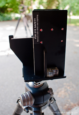
Before one can make a test image to determine any front or back-focus, one must first place the camera and LensAlign on separate platforms, space them, and make them square to one another.
It really helps to have the LensAlign either indoors with indirect lighting, but I suppose if you’re feeling motivated, you could set up flashes to illuminate it. When using it outdoors, be sure to place the unit in shade, or use it on an overcast day. The ruler is extremely reflective, and direct sunlight turns it into a blinding mirror. You want the light falling on the ruler to be even for easy-reading!
The online distance tool helps to determine how far apart the camera should be from the LensAlign, as well as how “deep” the DOF should be with a given focal length and sensor size. This distance can also be calculated manually by multiplying the focal length by 25. So, for a 400mm lens, one would need to be 10,000mm from the target, or 32.8 feet. TIP: A 50-foot reel measuring tape will be very helpful for this step if you own telephoto lenses!
I have also tried calibrating lenses at their minimum focusing distance (MFD) instead of the recommended distance. In a way, it’s easier because one just moves back as far as one needs in order to get LensAlign in focus. Additionally, the target will be larger in the frame the closer one is to it, making the markings on the ruler easier to read. In fact, in my first draft of this review, I suggested that MFD might be all you need. But then I was proven wrong!
My advice for telephoto lenses 400mm and longer would be to first make an adjustment for the MFD, and then back up to the suggested distance to confirm the adjustment. I recently calibrated a 500mm f/4L with my 1D Mark III and discovered that the adjustment made to counteract back-focus at MFD was too extreme, and actually caused front-focus when set at 41 feet from the target.
Aligning LensAlign
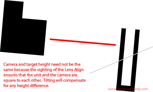
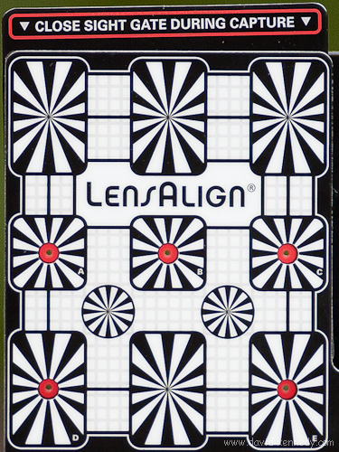
The first step you should take is use your tripod head (you have to be tripod-mounted) to position the camera at the LensAlign. Aim the center focusing point (the most accurate of the focusing points, irrespective of camera brand or model) at the center bulls-eye of LensAlign. Then, run behind the LensAlign, and looking through the “peep hole” through the center bulls-eye, lock it in position so that you are looking through the center of the lens. Often, you can see light coming in through the viewfinder of the camera through the middle of the lens, which can help to make it just right.Return to the camera, and switch on Live View (or take a picture and review it on the LCD) and zoom in to see if the center bulls-eye is truly centered in its viewing port.
An aside:To my knowledge, every camera that has the ability to make AFMA changes also has live view. However, the LensAlign is helpful even with cameras that do not have this feature, as it can confirm whether or not there is a focus problem with a given lens. If there is a problem, the user can take the data and decide whether the front or back-focus exhibited warrants sending the camera and lens to the manufacturer to be professionally calibrated.
While the LensAlign manual does explain how to make the unit square to a camera, I have found that it helps to pay attention to more than the center bulls-eye, but to consider all of them. Especially at shorter distances and wider focal lengths, the other four bulls-eyes will not be centered in their viewing ports, but making sure that they are symmetrical on opposite sides of the center bulls-eye ensures that the plane of the LensAlign is parallel to the camera’s sensor plane.
Corrections and A note about Keeping Things Level
In the original version of this review, incorrectly stated that the body of the LensAlign is made from black masonite. While it has that apperance, it is actually made from PVC.
Additionally, in the original posting I emphasized that keeping both the camera and LensAlign level, by means of a hot shoe bubble level or otherwise, would be a good idea.
After speaking to Michael Tapes directly, I stand by thinking that it’s helpful to keep things level, but agree that it is not essential for the operation of LensAlign. Hence, I have removed it from the section about aligning the focus target to the camera lens. In fact, he told me that the absence of a level “wasn’t a casual omission.” He believes that adding a level the product would make it appear to the user that being level was part of making the camera and focus target square, when it is not, in fact, a necessary step.
A level camera and a level focusing target will not change the DOF–it’s a constant. Camera lenses do not draw rectangular images, but circular ones, so how the camera is rotated on the lens doesn’t change the DOF. However, I find that leveling both helps in reviewing the images from LensAlign, because my beleaguered brain doesn’t like to look at picture of a ruler that is skewed at a 5° angle.
For me, I find the lack of a level to be my lone frustration with the product. I say this because it is downright annoying to constantly walk back and forth between the camera and the LensAlign while trying to remember to take the level with me each time. When I walked 41 feet out to the 500mm lens that I was trying to make square to the focus target, and realized that the level was still sitting on the back of the LensAlign, I really started grousing!
But to reiterate: it is not necessary to do this extra step of leveling the two devices, I just prefer to work this way, and I think many photographers who will take the time to change the AFMA in their cameras will feel the same as I do that looking at a level measurement tool is easier than looking at one that is tilted, even if the data is the same.

Fantastic writeup! Very informative!
[…] the fall of 2010, while reviewing a LensAlign Pro on loan from Michael Tapes Design, it was hinted that a new product was coming that […]
[…] is a continuation of my two-part review of the LensAlign Pro. You may wish to refer to part one before […]